8051 Microcontroller
The complete guide to Intel's 8051 architecture - the classic 8-bit MCU that shaped embedded systems

The complete guide to Intel's 8051 architecture - the classic 8-bit MCU that shaped embedded systems
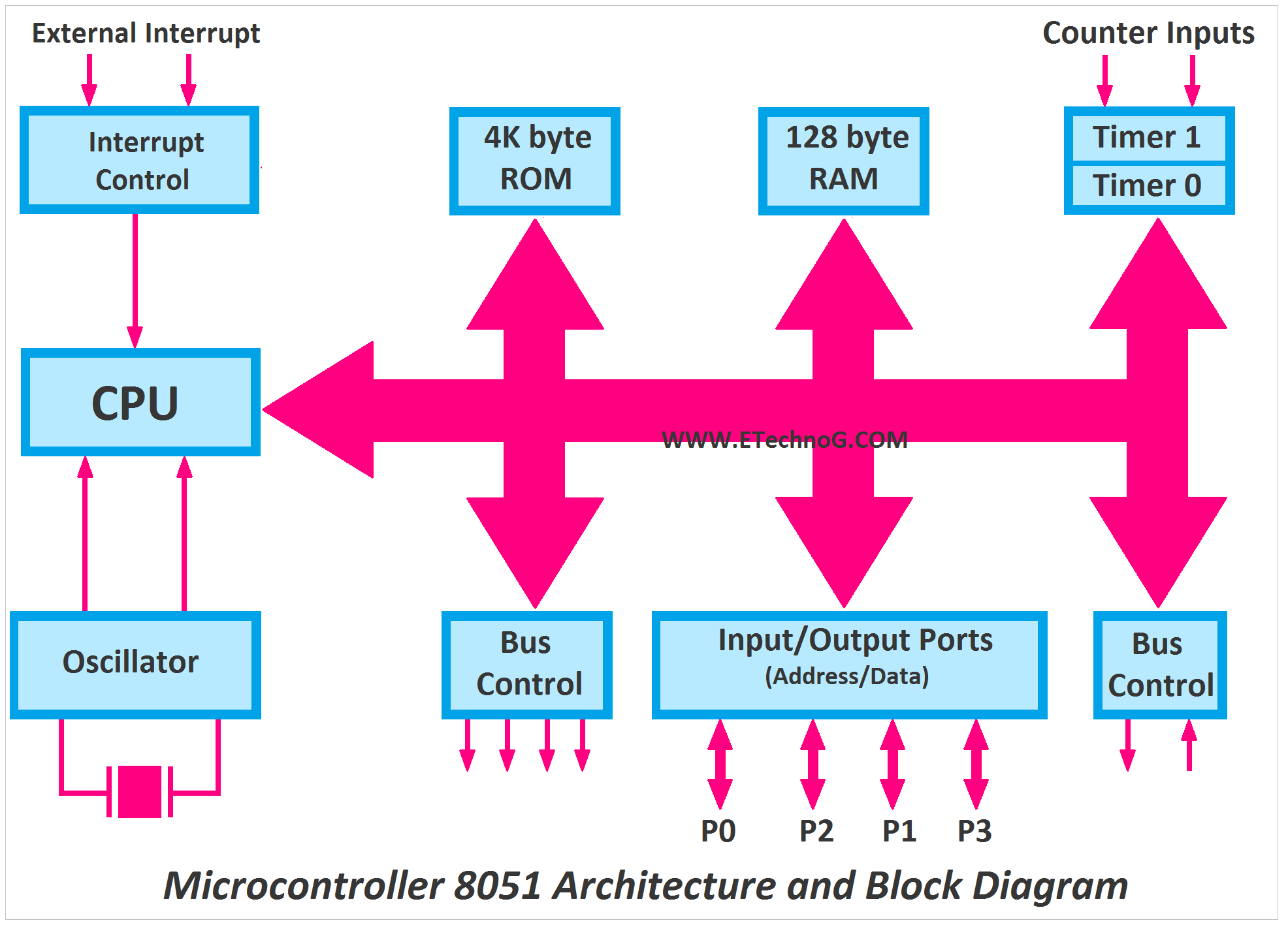
The Intel 8051 is an 8-bit microcontroller developed in 1980 that became an industry standard. Its Harvard architecture and rich instruction set made it popular for embedded systems.
The 8051 architecture has been implemented by many manufacturers with various enhancements:

The original microcontroller from Intel


| Memory Type | Size | Address Range | Access Method |
|---|---|---|---|
| Program Memory (ROM) | 4KB (up to 64KB) | 0000H-0FFFH | MOVC A,@A+DPTR |
| Internal RAM | 128B (256B in some) | 00H-7FH (00H-FFH) | Direct/Indirect |
| Special Function Registers | 128B | 80H-FFH | Direct |
| External RAM | Up to 64KB | 0000H-FFFFH | MOVX |
| SFR | Address | Function | Bit-Addressable |
|---|---|---|---|
| ACC | E0H | Accumulator | Yes |
| B | F0H | B Register | Yes |
| PSW | D0H | Program Status Word | Yes |
| SP | 81H | Stack Pointer | No |
| P0 | 80H | Port 0 | Yes |
| TCON | 88H | Timer Control | Partially |
; Sample 8051 Assembly Program
ORG 0000H       ; Start at address 0000H
LJMP MAIN     ; Jump to main program

ORG 0030H       ; Main program starts here
MAIN:
    MOV A, #55H   ; Load 55H into accumulator
    MOV P1, A     ; Output to Port 1
    ACALL DELAY   ; Call delay subroutine
    MOV A, #0AAH
    MOV P1, A
    ACALL DELAY
    SJMP MAIN    ; Repeat forever

DELAY:
    MOV R0, #0FFH ; Delay subroutine
DELAY_LOOP:
    DJNZ R0, DELAY_LOOP
    RET

END// Blink LED on P1.0
#include <reg51.h>
#include <stdio.h>
void delay(unsigned int time) {
unsigned int i,j;
for(i=0;i<time;i++)
for(j=0;j<1275;j++);
}
void main() {
while(1) {
P1_0 = 1; // LED ON
delay(1000);
P1_0 = 0; // LED OFF
delay(1000);
}
}| Mode | Example | Description |
|---|---|---|
| Immediate | MOV A, #25H | Data is part of instruction |
| Register | MOV R0, A | Data in register |
| Direct | MOV A, 40H | Data at memory location |
| Indirect | MOV A, @R0 | Register holds address |
| Indexed | MOVC A, @A+DPTR | Base + offset address |
8051 has two 16-bit timers (Timer 0 and Timer 1) that can be used as:
// Timer 0 as interval timer (Mode 1)
#include <reg51.h>

void timer0_isr() interrupt 1 {
    TH0 = 0x3C;    // Reload for 50ms @ 11.0592MHz
    TL0 = 0xB0;
    P1_0 = ~P1_0;  // Toggle pin
}

void main() {
    TMOD = 0x01;   // Timer 0, Mode 1
    TH0 = 0x3C;    // Initial values
    TL0 = 0xB0;
    TR0 = 1;       // Start timer
    ET0 = 1;       // Enable timer interrupt
    EA = 1;        // Global interrupt enable

    while(1);      // Infinite loop
}8051 has a full-duplex UART for serial communication:
// Serial Echo Program
#include <reg51.h>

void serial_isr() interrupt 4 {
    if (RI) {
        RI = 0;            // Clear receive flag
        SBUF = SBUF;       // Echo received byte
        while(!TI);      // Wait for transmit
        TI = 0;            // Clear transmit flag
    }
}

void main() {
    TMOD = 0x20;   // Timer 1, Mode 2 (auto-reload)
    TH1 = 0xFD;    // 9600 baud @ 11.0592MHz
    SCON = 0x50;   // Serial Mode 1, enable reception
    TR1 = 1;       // Start timer
    ES = 1;        // Enable serial interrupt
    EA = 1;        // Global interrupt enable

    while(1);      // Infinite loop
}8051 has 5 interrupt sources with fixed priorities:
| Interrupt | Vector Address | Flag | Enable Bit |
|---|---|---|---|
| External 0 (INT0) | 0003H | IE0 | EX0 |
| Timer 0 (TF0) | 000BH | TF0 | ET0 |
| External 1 (INT1) | 0013H | IE1 | EX1 |
| Timer 1 (TF1) | 001BH | TF1 | ET1 |
| Serial (RI/TI) | 0023H | RI/TI | ES |