LDR (Light Dependent Resistor) Sensors
Complete guide to light sensing with LDR photoresistors
Complete guide to light sensing with LDR photoresistors
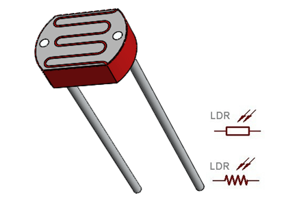
LDRs (Light Dependent Resistors) are passive electronic components whose resistance decreases with increasing light intensity.

| Maximum Voltage | 150V (typical) |
| Power Dissipation | 100mW (max) |
| Operating Temperature | -30°C to +70°C |
| Spectral Range | 400nm-700nm |
| Resistance Tolerance | ±20% |


The standard way to use an LDR is in a voltage divider configuration with a fixed resistor:
Typical resistor values: 10kΩ works well for most applications

// Basic LDR Sensor Example
#define LDR_PIN A0

void setup() {
    Serial.begin(9600);
}

void loop() {
    int ldrValue = analogRead(LDR_PIN);
    Serial.print("LDR Value: ");
    Serial.println(ldrValue);

    // Simple threshold detection
    if(ldrValue < 500) {
        Serial.println("Dark environment");
    } else {
        Serial.println("Bright environment");
    }

    delay(1000);
}// LDR with auto-calibration
#define LDR_PIN A0
#define CALIBRATION_TIME 5000 // 5 seconds
int minLDR = 1023;
int maxLDR = 0;
void setup() {
Serial.begin(9600);
calibrateSensor();
}
void calibrateSensor() {
Serial.println("Calibrating - expose sensor to min and max light");
unsigned long startTime = millis();
while(millis() - startTime < CALIBRATION_TIME) {
int val = analogRead(LDR_PIN);
if(val < minLDR) minLDR = val;
if(val > maxLDR) maxLDR = val;
delay(100);
}
Serial.print("Calibration complete. Min: ");
Serial.print(minLDR);
Serial.print(" Max: ");
Serial.println(maxLDR);
}
void loop() {
int ldrValue = analogRead(LDR_PIN);
int normalized = map(ldrValue, minLDR, maxLDR, 0, 100);
Serial.print("Light Level: ");
Serial.print(normalized);
Serial.println("%");
delay(500);
}// Automatic light control with LDR and relay
#define LDR_PIN A0
#define RELAY_PIN 3
#define THRESHOLD 300 // Adjust based on your LDR
void setup() {
pinMode(RELAY_PIN, OUTPUT);
}
void loop() {
int ldrValue = analogRead(LDR_PIN);
if(ldrValue < THRESHOLD) {
digitalWrite(RELAY_PIN, HIGH); // Turn lights on
} else {
digitalWrite(RELAY_PIN, LOW); // Turn lights off
}
delay(10000); // Check every 10 seconds
}LED light that turns on automatically when dark.
Measure and display light levels on LCD or OLED.
Automatically open/close curtains based on sunlight.
Trigger camera when light changes (lightning, etc.).
Monitor and log light exposure for plants.
Trigger alarm if light is detected when it should be dark.
// Components needed:
- Multiple LDR sensors (different locations)
- Arduino/ESP32
- Relay module
- LED lighting system
- OLED display
- Real-time clock

// Features:
1. Monitor ambient light at multiple points
2. Automatically adjust artificial lighting
3. Maintain consistent light levels
4. Energy saving algorithm
5. Data logging
6. Time-based control profiles

// Implementation Tips:
- Use multiple LDRs for better coverage
- Implement PID control for smooth adjustments
- Add manual override capability
- Create energy usage reports
- Add wireless control option
- Consider solar input for outdoor applications| Mistake | Consequence | Solution |
|---|---|---|
| Wrong resistor value | Limited measurement range | Choose resistor based on expected light levels |
| No calibration | Inconsistent performance | Always calibrate in actual environment |
| Direct sunlight exposure | Saturation or damage | Use diffuser or limit exposure |
| Ignoring response time | Missed rapid light changes | Account for 100ms response time |
| Single sensor for large area | Inaccurate light measurement | Use multiple sensors for better coverage |